Making my own GPU ! Part-1
It was my long time interest to know how a GPU works. Well the best way to know how it works is to create one.
Now to figure out how to make one
What do i know ?
1) GPU outputs to display
2) There is some sort of parallel processing in GPUs
3) There is something called as a frame-buffer which stores the entire frame in memory
Lets ask chat gpt on how it works
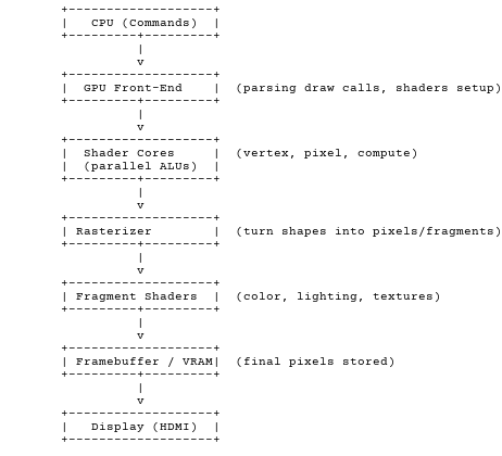
CPU sends commands → GPU breaks them down → shader cores do math in parallel → rasterizer makes pixels → framebuffer stores → display shows.
Now we learned a new word rasterizer
>CHAT GPT EXPLAIN RASTERIZER!!!
Great question 🙂
The rasterizer is one of the most important fixed-function stages of a GPU pipeline. Let’s break it down in simple terms:
🔹 What it does
The rasterizer takes shapes made of vertices (usually triangles) and turns them into fragments (potential pixels) that can be drawn on the screen.
Think of it like this:
- Vertices = 3D coordinates of a triangle in space (after vertex shaders transform them).
- Rasterizer = “paints” that triangle onto the 2D pixel grid of your screen.
- Output = a bunch of fragments (one per pixel covered by the triangle).
🔹 Steps of Rasterization
- Triangle Setup
- The GPU knows where the triangle’s vertices are in screen space.
- It calculates the triangle’s edges, slopes, and bounding box.
- Pixel Coverage Test
- For each pixel inside the triangle’s bounding box, it checks: “Is this pixel inside the triangle?”
- If yes → generate a fragment for it.
- Attribute Interpolation
- Each vertex might have extra data (color, texture coordinates, depth).
- Rasterizer smoothly interpolates these values across the triangle.
Example: If one vertex is red, another is blue, pixels between them will be purple.
- Depth & Scissor Tests (optional)
- Some early rejection can happen before sending fragments forward (like if it’s behind another triangle or outside a viewport).
🔹 ASCII analogy
Imagine a triangle drawn on a sheet of graph paper (the pixel grid):
Vertices:   o
           / \
          /   \
         o-----o
The rasterizer is the process of filling in which grid squares (pixels) are inside the triangle, and for each filled square, figuring out its color, texture, and depth.
🔹 Output
The rasterizer doesn’t directly decide the final color.
Instead, it passes fragments (with interpolated attributes) to the fragment shader, which then computes the final pixel value (textures, lighting, etc.).
👉 So in one line:
Rasterizer = turns triangles into per-pixel fragments + interpolated data for shading.
Do you want me to also make a tiny ASCII diagram of where the rasterizer sits in the pipeline (between shaders and fragment stage), so it’s easier to visualize?

>NOOO CHATGPT TOO MANY TEXT ELI5 pls
Got it 🙂 — here’s the “Explain Like I’m 5” version of the rasterizer:
Imagine you have a coloring book with triangle outlines, and a piece of graph paper underneath.
- The triangle outline = what the GPU got from the vertex stage.
- The graph paper = your screen, made of little squares (pixels).
- The rasterizer = the person with a crayon who goes through each square and asks:
👉 “Is this square inside the triangle?”
- If yes → color it in.
- If no → leave it blank.
While coloring, the rasterizer also blends the colors from the triangle’s corners so the inside looks smooth.
🖼️ Simple picture:
Triangle outline:
     /\
    /  \
   /____\

Screen pixels:
 ##########
 ##########
 ##########
 ##########

Rasterizer result:
     XX
    XXXX
   XXXXXX
So, the rasterizer’s job is just to turn triangle outlines into filled-in pixels on your screen.
>Okay! now how can a gpu be parallel computing ?
Okay, let’s go full ELI5 mode on how a GPU does parallel compute 🚀
🧩 Puzzle Analogy
Imagine you have a huge puzzle with 1000 pieces.
- A CPU is like one smart kid who puts the puzzle together piece by piece.
- A GPU is like 1000 kids sitting around the table, and each kid is told:
👉 “You handle just one piece!”
That way, the puzzle gets done much, much faster.
🏗️ What the GPU actually does
- The GPU has thousands of tiny workers (called cores).
- Instead of one core doing everything (like a CPU), the GPU splits a big problem into many small problems.
- Each worker solves its little part at the same time.
- Finally, the results are combined into the final answer (like the finished puzzle or an image on screen).
🎮 Example (video game pixels)
Suppose your screen has 1 million pixels to draw:
- A CPU might draw them one by one.
- A GPU assigns each pixel (or group of pixels) to a different worker.
- All pixels get drawn at the same time → smooth graphics.
🍫 Candy Factory Analogy
Think of a chocolate factory 🍫:
- CPU = 1 chef making chocolates one at a time.
- GPU = 1000 workers, each dipping one chocolate at the same time.
- End result = huge batch finished quickly.
👉 In short:
A GPU works like a giant classroom full of kids all solving math problems at once, while a CPU is like one genius solving them alone.
>Nice is this what tile based rendering is ??
Ahh, you nailed the connection 👌 — yes, tile-based rendering is related to this idea of breaking things into smaller pieces and processing them in parallel. Let me ELI5 it with your GPU context:
🔹 Normal (immediate mode) rendering
Imagine painting a huge wall:
- You dip your brush and try to paint the entire wall row by row.
- You constantly need to check: “Is there something already here? Is it behind something else?”
- This wastes effort and memory (lots of back-and-forth).
🔹 Tile-based rendering
Instead, you split the wall into small tiles (like bathroom tiles 🟦🟦🟦).
- Each worker (GPU core group) takes one tile.
- It paints only that tile, keeping track of what belongs there in a small “scratchpad” memory.
- Once finished, the tile is sent to the framebuffer.
- Then it moves on to the next tile.
This means:
- Less wasted memory bandwidth.
- Easier to parallelize (many tiles can be rendered at once).
- Very power-efficient (why phones and embedded GPUs love this method 💡).
🔹 ASCII analogy
Screen = Big Image
+---------------------+
|  Tile1 |  Tile2    |
|--------+-----------|
|  Tile3 |  Tile4    |
+---------------------+

GPU works on each tile separately,
often in parallel.
👉 So:
- Parallel compute = GPU has thousands of workers doing little jobs at once.
- Tile-based rendering = Instead of drawing the whole screen at once, the GPU divides it into tiles and renders each tile independently (and often in parallel).
HMMMMMM lets get all the details we gather
- tile based rendering split scene into small tiles and render and sent the framebuffer back which will be stitched together
- rasterization converting triangles into pixels
SO this is a distributed computing problem! Yessshhhhhhh lets gooooooooooooo
i want a easy to work with hardware which is cheap sooo some sort of esp 32
and i want to do 640x480@60Fps
No esp directly has hdmi o/p but u can get a hdmi shield like http://www.techtoys.com.hk/BoardsKits/HDMIshield/HDMIshield.htm
But i for the sake of god figure out how to buy from them
So what else option do i have ?? use a board with hdmi
Like https://www.cnx-software.com/2015/11/24/fleafpga-uno-board-combines-a-lattice-fpga-arduino-uno-form-factor-hdmi-output-and-an-esp8266-wifi-module/
But no its costly
Okay so i need a bridge board then i saw https://codeandlife.com/2012/12/27/raspberry-pi-as-arduino-hdmi-shield/
neat idea but i dont want to work with a full fledged OS it seems overkill
SOOOOOOO....what else i searched and asked chatgpt it suggested a FPGA to be more precise https://en.wiki.sipeed.com/hardware/en/tang/tang-nano-20k/nano-20k.html this was recommended ( after tinkering with it, i would suggest buy the 9k version it has more documentation and examples )
Okay now how do i send data to this fpga ? via UART initially then after a while try to change it to SPI ( as of writing i don't know if it is supported or how hard it would be to impliment )
How do I program this board dravid u might ask ..... verilog ofcourse is what a normal sane person would have suggested but hear me out !
What if there was a way i dont relearn
https://github.com/enjoy-digital/litex/wiki/LiteX-for-Hardware-Engineers
as it is in the wiki
What is LiteX?
LiteX is a Python "front-end" that generates Verilog netlists, and drives proprietary build "back-ends", such as Vivado or ISE, to create bitstreams ("gateware") for FPGAs.
LiteX is relies on a Python toolbox called Migen. In addition to a build environment, it provides a set of IP blocks. Some of the IP blocks include a DDR2/3 MIG equivalent, various softcore CPUs (lm32, openrisc, RISCV), Ethernet controller, HDMI input/output, Wishbone routing fabrics, streams, and PCI express.
LiteX naively supports Linux/x86. It requires Python3.5 or later. You’ll need to manually download, install, and provision your back-end tools (e.g.: Vivado/ISE), and you’ll also need to install a gcc cross-compiler to any softcore CPU you plan to use in your designs. Details later.
Here’s the design flow in a nutshell:
Describe your design in Python using the migen toolbox and LiteX IP by customizing aModuleobject (typically by subclassingSoCSDRAM, which is a subclass ofSoCCorewhich subclasses the baseModuleclass)
Describe your build environment by customizing aPlatformobject (typically by subclassing theXilinxPlatformclass which itself sublcasses theGenericPlatformbase class)
Run a function which passes yourPlatformobject to aBuilderobject, and invokes thebuild()method which:
Creates a top.v file: a single, flat verilog netlist of your entire design modulo a few exceptions to be noted later.Creates a top.xdc file: constraints that locate pins, defines clocks, and eliminates false pathsIf a CPU is configured, generates and builds a BIOS binary to be compiled into the design
If a toolchain is configured, creates a top.tcl file which drives the proprietary synth/place/route/bitgen "backend" toolchainAttempts to run the proprietary back-end tool (Vivado will be assumed for this doc, but ISE is also supported)
Runmakein thefirmwaredirectory, which builds your firmware binary (firmware.bin).
Upload top.bit to the FPGA — typically over JTAG via openOCDUploadfirmware.binto the FPGA — typically via UART or Ethernet, using thefltermhost-native application and theserialbootcommand
Interact with your firmware’s REPL loop using flterm
If you designed a litescope into your design (an ILA like Chipscope), configure triggers and download traces using an analyzer script, which relies on a helper program called litex_server. Debugging occurs either through a supplementary UART or Ethernet that must be present in the hardware (either designed in or test leads connected to a header).Find bugs & go back to step 1!
LiteX-buildenv attempts to automate steps 3 and onwards. However, I don’t use the master script, it’s a bit too brittle yet for reliable development, so I tend to run each of the major steps one command at a time.
now now now dosent that sound intresting
Soo i played around using chatgpt to generate litex code which sounds insane but it works.
And my work is here . Since i found no examples for tang nano 20k with litex i created some
https://github.com/Dravigon/tang-nano-20k-litex-examples
Some of it might not work like the litescope and hyperbus but rest works
Now after days of work, finally i have hdmi o/p https://github.com/Dravigon/tang-nano-20k-litex-examples/blob/main/hdmi_test.py
And Sooo, ppl here we are now we make uart work https://github.com/Dravigon/tang-nano-20k-litex-examples/blob/main/uart.py
corresponding esp32-s3 code
#include <HardwareSerial.h>

// Use the built-in Serial2 rather than making a new object.
// (Serial2 is UART2 under the hood.)
void setup() {
  Serial.begin(115200);                      // USB to PC
  Serial2.begin(115200, SERIAL_8N1, 16, 17); // RX=16, TX=17
  Serial.println("Listening on Serial2 @115200, RX=16 TX=17...");
}

void loop() {
  while (Serial2.available()) {
    int c = Serial2.read();
    // Print ASCII + hex so you always see something
    Serial.print("RX: '");
    if (c >= 32 && c <= 126) Serial.write(c); else Serial.print('.');
    Serial.print("' 0x");
    if (c < 0x10) Serial.print('0');
    Serial.println(c, HEX);
  }
}
Next we mix both together https://github.com/Dravigon/tang-nano-20k-litex-examples/blob/main/uart_rx_frame_buffer.py
corresponding ardunio code for esp32-s3
// ESP32-S3 -> Tang Nano 20K
// Moving colored square + gradient background, 640x480 RGB565.
// Protocol: SOF (AA 44), then for each row: AA 55 'R' y_lo y_hi + 1280B, wait 'K'.
// EOF (AA 66), wait 'F' before starting next frame.

#include <Arduino.h>
#include <HardwareSerial.h>

// ---------- Link / geometry ----------
const uint32_t BAUD = 6000000;   // 6,000,000 baud
const int      HRES = 640;
const int      VRES = 480;

// ---------- Pins (adjust if needed) ----------
#define RX2_PIN 9   // ESP32-S3 RX (from FPGA TX)
#define TX2_PIN 10  // ESP32-S3 TX (to   FPGA RX)

// ---------- UART instance ----------
HardwareSerial& UART = Serial2;

// One scanline buffer: RGB565 (2 bytes / pixel)
static uint8_t rowbuf[HRES * 2];

// ------------------------------------------------------------
// Types (put BEFORE any function so Arduino's auto-proto knows them)
// ------------------------------------------------------------
struct Box {
  int x, y;       // top-left
  int w, h;
  int vx, vy;     // velocity in pixels/frame
};

// Global animation state
static Box g_box = { (HRES - 160)/2, (VRES - 160)/2, 160, 160, 10, 5 };
static uint32_t g_frame_idx = 0;

// ------------------------------------------------------------
// Utilities
// ------------------------------------------------------------
static inline void flushInputUART() {
  while (UART.available()) (void)UART.read();
}

static bool writeAll(const uint8_t* data, size_t len) {
  size_t off = 0;
  while (off < len) {
    size_t n = UART.write(data + off, len - off);
    if (n == 0) {
      // TX FIFO full: give UART a moment
      delayMicroseconds(150);
      continue;
    }
    off += n;
  }
  return true;
}

// Wait for a single expected byte (e.g. 'K' or 'F') with timeout.
// Returns true on match, false on timeout/mismatch.
static bool waitForByte(uint8_t expected, uint32_t timeout_ms) {
  uint32_t start = millis();
  while ((millis() - start) < timeout_ms) {
    if (UART.available()) {
      int c = UART.read();
      if (c == (int)expected) return true;
      // Ignore any other bytes (drain garbage/stale)
    }
    delayMicroseconds(100);
  }
  return false;
}

// ------------------------------------------------------------
// Protocol helpers
// ------------------------------------------------------------
static inline void sendSOF() {
  const uint8_t sof[2] = { 0xAA, 0x44 };
  writeAll(sof, sizeof(sof));
}

static inline bool sendRow(uint16_t y, const uint8_t* payload) {
  // Header: AA 55 'R' y_lo y_hi
  uint8_t hdr[5];
  hdr[0] = 0xAA;
  hdr[1] = 0x55;
  hdr[2] = 'R';
  hdr[3] = uint8_t(y & 0xFF);
  hdr[4] = uint8_t((y >> 8) & 0xFF);

  // Send header + 1280B payload
  if (!writeAll(hdr, sizeof(hdr))) return false;
  if (!writeAll(payload, HRES * 2)) return false;

  // Wait for row ACK 'K'
  return waitForByte('K', /*timeout_ms=*/100); // ~2.13 ms per row @ 6 Mbaud; 100 ms is generous
}

static inline bool sendEOF() {
  const uint8_t eof[2] = { 0xAA, 0x66 };
  writeAll(eof, sizeof(eof));
  return waitForByte('F', /*timeout_ms=*/200);
}

// ------------------------------------------------------------
// RGB565 helpers
// ------------------------------------------------------------
static inline uint16_t pack565(uint8_t r8, uint8_t g8, uint8_t b8) {
  // 8-bit -> 5/6/5
  uint16_t r = (r8 >> 3) & 0x1F;
  uint16_t g = (g8 >> 2) & 0x3F;
  uint16_t b = (b8 >> 3) & 0x1F;
  return uint16_t((r << 11) | (g << 5) | (b << 0));
}

// ------------------------------------------------------------
// Animation helpers
// ------------------------------------------------------------
static void updateBox(Box& b) {
  b.x += b.vx;
  b.y += b.vy;
  if (b.x < 0) { b.x = 0; b.vx = -b.vx; }
  if (b.y < 0) { b.y = 0; b.vy = -b.vy; }
  if (b.x + b.w > HRES) { b.x = HRES - b.w; b.vx = -b.vx; }
  if (b.y + b.h > VRES) { b.y = VRES - b.h; b.vy = -b.vy; }
}

// Fills rowbuf for scanline y using a gradient background and a moving box.
// Box color changes every frame (based on g_frame_idx).
static void fillRow(uint16_t y, const Box& b, uint32_t frame_idx) {
  // Box color cycles each frame
  const uint8_t sqR = uint8_t((frame_idx * 3) & 0xFF);
  const uint8_t sqG = uint8_t((frame_idx * 5) & 0xFF);
  const uint8_t sqB = uint8_t((frame_idx * 7) & 0xFF);

  // Precompute the row’s background G component from y for a vertical gradient
  const uint8_t gbg = uint8_t((uint32_t(y) * 255) / (VRES - 1));  // 0..255

  uint8_t* p = rowbuf;
  const bool rowHitsBox = (y >= b.y) && (y < b.y + b.h);

  if (rowHitsBox) {
    // Fast path: split the row into 3 segments (left background, box, right background)
    const int x0 = b.x;
    const int x1 = b.x + b.w;  // exclusive
    // left segment
    for (int x = 0; x < x0; ++x) {
      uint8_t rbg = uint8_t((uint32_t(x) * 255) / (HRES - 1));
      uint8_t bbg = uint8_t((x ^ y) & 0xFF);
      uint16_t pix = pack565(rbg, gbg, bbg);
      *p++ = uint8_t(pix & 0xFF);
      *p++ = uint8_t((pix >> 8) & 0xFF);
    }
    // box segment (solid color)
    uint16_t boxpix = pack565(sqR, sqG, sqB);
    for (int x = x0; x < x1; ++x) {
      *p++ = uint8_t(boxpix & 0xFF);
      *p++ = uint8_t((boxpix >> 8) & 0xFF);
    }
    // right segment
    for (int x = x1; x < HRES; ++x) {
      uint8_t rbg = uint8_t((uint32_t(x) * 255) / (HRES - 1));
      uint8_t bbg = uint8_t((x ^ y) & 0xFF);
      uint16_t pix = pack565(rbg, gbg, bbg);
      *p++ = uint8_t(pix & 0xFF);
      *p++ = uint8_t((pix >> 8) & 0xFF);
    }
  } else {
    // Entire row is background
    for (int x = 0; x < HRES; ++x) {
      uint8_t rbg = uint8_t((uint32_t(x) * 255) / (HRES - 1));
      uint8_t bbg = uint8_t((x ^ y) & 0xFF);
      uint16_t pix = pack565(rbg, gbg, bbg);
      *p++ = uint8_t(pix & 0xFF);
      *p++ = uint8_t((pix >> 8) & 0xFF);
    }
  }
}

// ------------------------------------------------------------
// Arduino setup/loop
// ------------------------------------------------------------
void setup() {
  Serial.begin(115200);
  delay(200);

  UART.begin(BAUD, SERIAL_8N1, RX2_PIN, TX2_PIN);
  delay(50);

  Serial.println("ESP32-S3 Frame TX @ 6,000,000 baud (RGB565, 640x480)");
  Serial.printf("Pins: RX=%d, TX=%d\n", RX2_PIN, TX2_PIN);

  flushInputUART();
}

void loop() {
  uint32_t t0 = millis();
  uint32_t rows_ok = 0, rows_fail = 0;

  sendSOF();

  for (uint16_t y = 0; y < VRES; ++y) {
    fillRow(y, g_box, g_frame_idx);

    // Send the row; retry once on timeout
    bool ok = sendRow(y, rowbuf);
    if (!ok) {
      // brief pause and one retry (helps if FPGA WB bus is momentarily busy)
      delayMicroseconds(400);
      ok = sendRow(y, rowbuf);
    }
    if (ok) rows_ok++; else rows_fail++;

    // Optional tiny pacing if your link is noisy:
    // delayMicroseconds(100);
  }

  bool eof_ok = sendEOF();

  // Update animation for next frame
  updateBox(g_box);
  g_frame_idx++;

  // Optional: debug stats
  uint32_t t1 = millis();
  Serial.printf("Frame %lu: %lums, rows ok=%lu, fail=%lu, eof=%s, box=(%d,%d)\n",
                (unsigned long)g_frame_idx,
                (unsigned long)(t1 - t0),
                (unsigned long)rows_ok,
                (unsigned long)rows_fail,
                eof_ok ? "OK" : "TIMEOUT",
                g_box.x, g_box.y);

  // No extra delay — keep pumping frames as fast as UART allows.
}
okay now we got a Square rendering from esp32-s3 YAY !
Nice for now ... enough work i gotta rest and figure out something else like you know the next part ..... coming sooonnnnnnnn

Comments ()